COMMINUTION
Size reduction by particle breakage
▪ liberation
• Create
particles in certain size and
shape
• Increase surface area
available for next
process
Comminution usually accounts for more than ____ total power
40 % to 50%
Only about ____ of the energy input is used to comminute
3% – 5 %
Problems associated with comminution:
➢ It is mechanically a wasteful process.
➢ Most of the energy
input is lost to a lot of factors.
▪ Absorbed by the
equipment
▪ Water resistance in pulp
▪ Deformation (not
breakage) of plastic particles
➢ Heat is unavoidably produced.
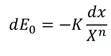
An empirical relationship between energy consumed during size reduction and particle size.
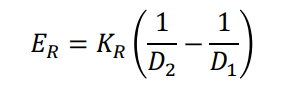
Rittinger’s Law
energy of breakage ∝ amount
of new surfaces produced
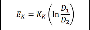
Kick’s Law
energy required ∝ reduction in volume of the particles concerned
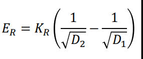
Bond’s Law
energy required ∝ new crack
tip length produced in particle
breakage
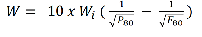
Work Index
Energy required to reduce one ton of ore from a very large size to 100µm
Jaw Crusher
1) Blake
2) Dodge Type
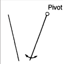
BlakeS
Movable jaw is pivoted at the top
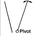
Dodge Type
Movable jaw is fixed at the bottom
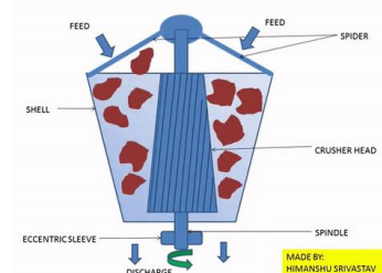
Relative motion of the crushing faces is
due to gyration motion
of an
eccentrically mounted cone
gyratory crusher
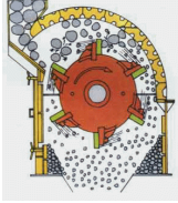
Comminution by impact; sharp blows on free-falling rock
IMPACTORS
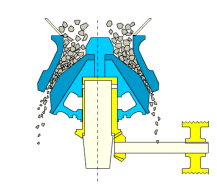
Modified gyratory crusher that yields smaller product
CONE CRUSHERS

Consists of two horizontal cylinders
revolving towards each other
ROLL CRUSHERS
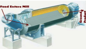
GRINDING
Last stage in comminution
process
Grinding Size Reduction
impact + abrasion
What is used when grinding
medium is present
balls or rods
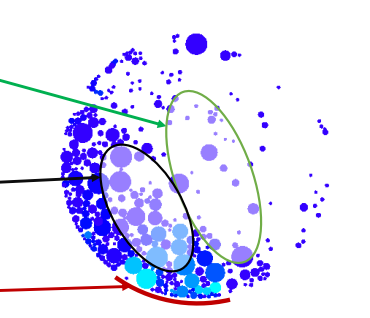
Green
• Parabolic path taken by charge as
projected by lifting of
the mill
• Coarse grinding by impact
Cataracting
Black
• Rolling motion of the charge down to
the toe
• Leads
to finer grinding by abrasion
Cascading
Red
Charge is carried around in a fixed
position
Centrifuging
Uses cast iron rods
as grinding medium
Rod Mill
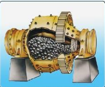
Uses forged steel
balls as grinding
medium
Ball Mill
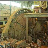
The action of the ore grinding upon itself with small amount of ball charge
Semi-autogenous Mill
SIZING
Selection of materials based on their size
SCREENING (Industrial Screening)
Use of screening equipment (screens)
• Extensively used for size separations from 300 mm down to
roughly 40 µm, efficiency decreases rapidly with fineness
Screen equipment are classified as
stationary and moving
SCREENING objectives
To optimize the feed of the comminution stage by preventing
the
materials which are already smaller, not to enter this
stage
• To ensure that the desired product is according to the
size
application
• To ensure that the feed to succeeding
process does not exceed
size limitation of receiving area
Sizing/Classifying
To separate particles by size
Scalping
To remove coarsest size fractions in the feed material
Grading
To prepare a number of products within specified size ranges
Media recovery
For washing magnetic media from ore in dense medium circuits; or to retain grinding media inside grinding mills
Dewatering
To drain free moisture from a wet sand slurry
De-sliming/De-dusting
To remove fine material, generally below 0.5 mm, from a wet or dry feed
Trash removal
Usually to remove coarse wood fibers or tramp material from a slurry stream
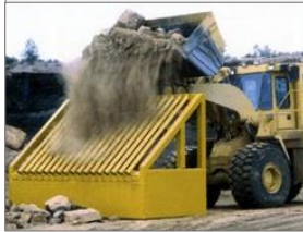
Static Grizzlies
• 35 – 50° deck angle
• Uses heavy parallel bars
• Used
with coarse crushing
(scalping operations)
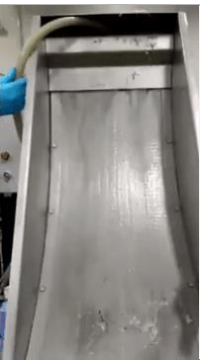
Sieve Bends
• >50μm, 180m3/hr
• Curved screen w/ horizontal
wedge
bars
• Slurry enters tangentially to
the bend
• Peeling
action of the slurry
bed
stationary screens
1. Static Grizzlies
2. Sieve Bends
moving screens
Grizzly Screens
Trommels
Grizzly Screens
• Usually screens very coarse
material
• Characterized by
parallel steel
bars on rails set at a fixed
distance apart
and installed in
line with the flow of ore
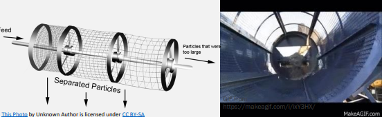
Trommels
• Comprised of a cylindrical screen
• Can be made to deliver
sized
products by using a series from
finest to coarsest or
using
concentric trommels with the
coarsest mesh being innermost
CLASSIFICATION
LESS Than 1mm
Method of separating mixtures of minerals into 2 or more
products based on the velocity of the particles as the grains
fall
through a fluid medium (liquid or gas)
Wet classification
usually uses water, generally applied to
mineral particles
considered too fine to be sorted efficiently by screening
CLASSIFIERS
• used for particles 1mm or less
CLASSIFIERS categorized by force field applied to unit
either gravitational or centrifugal
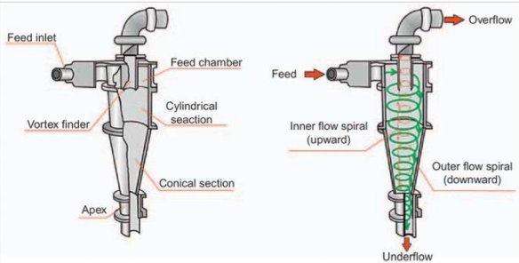
Hydrocyclone
Utilizes centrifugal force to accelerate settling rate of particless
gravitational classifiers
Spiral Classifier
Rake Classifier
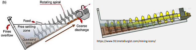
Spiral Classifier
A continuously revolving spiral moves the sands up the slope
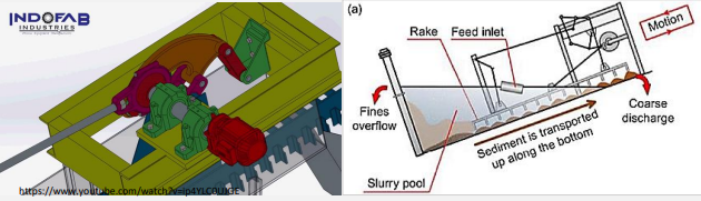
Rake Classifier
Uses rakes actuated by an eccentric motion, which causes them to dip into the settled material and move up the incline for a short distance
GRAVITY CONCENTRATION
• Most simple and economical of all concentration methods
•
Particles are separated by their differences in density
• Greater
density difference = easier separation
Dense Media
Separation
Particles are placed in a
liquid of known density.
Denser
particles sink
while lighter particles float
Vertical Current
Separation
Stratification of mineral
layers based on their
densities
on a particle
bed, fluidized by a stream
of water
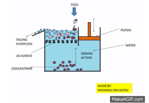
Jigging
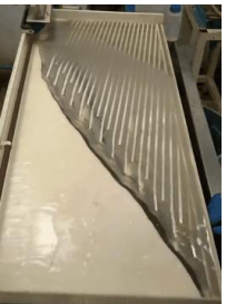
Shaking Table
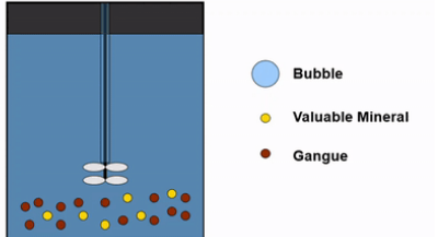
Separation via altering surface-chemical properties of minerals
bubbles
FROTH FLOTATION
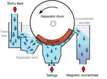
• Uses the difference in magnetic
properties between minerals
Magnetic Separation
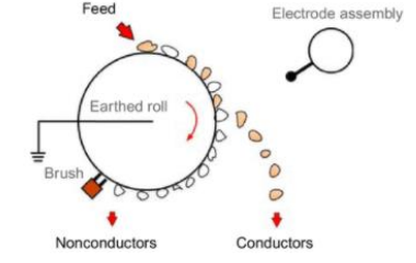
Uses the difference in electrical
conductivities between minerals
High Tension Separation
DEWATERING
Solid – Liquid Separation
• Produces a relatively
dry
concentrate (less shipping
volume)
• For certain
processes that
requires low H2O content
Dewatering (combination of the
three)
Sedimentation
Filtration
Thermal Drying
Sedimentation
Increases concentration
of suspensions by
settling solids
Filtration
Uses a porous medium that blocks solids (filter cake) and allows liquids (filtrate) to pass through.
Thermal Drying
Final operation in a mineral processing
plant. Moisture content
is lowered to ~5 wt%
Sedimentation
Coagulation
Flocculation
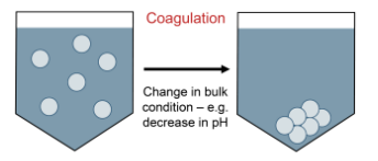
Coagulation
Neutralizes charged particles so that they
will settle and not
continuously repel each other
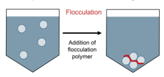
Flocculation
Uses long-chain polymers to bridge particles until they areheavy enough to settle
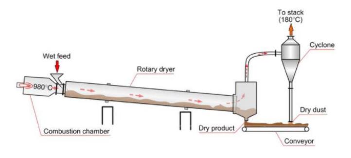
THERMAL DRYING | rotary dryer
ORE HANDLING
Costs account for 30 – 60% of total delivered price of raw materials
• Covers the processes of transportation, storage, feeding,
washing, and sampling of the ore en route to, or during its
various
stages of treatment in the mill
ORE TRANSPORTATION
Minimum upward and horizontal movement
• Maximum practicable
pulp density
ORE TRANSPORTATION (Basic Philosophy)
• The use of gravity should be maximized.
• There should be
continuous movement.
• Shortest possible distances in between
processing units should be
utilized.
ORE TRANSPORTATION | dry ore
Chutes
(Standard Rubber) Belt Conveyor
Gravity Bucket Elevators
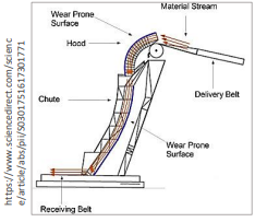
Chutes
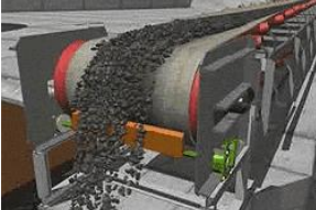
(Standard Rubber) Belt Conveyor
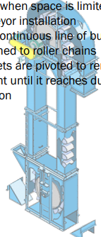
Gravity Bucket Elevators
ORE STORAGE
Necessity arises from successive processing units performing
at
different rates
▪ Intermittent vs. continuous, for
repairs, and for successive batch and
continuous processes
ORE STORAGE Depends on
▪ The equipment in the mill / method of operation
▪ Frequency of
maintenance work required
ORE STORAGE Accomplished by having
stockpiles, and using bins or tanks
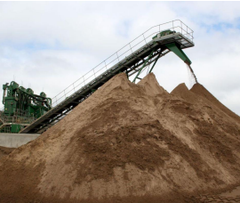
ORE STORAGE
Stockpiles
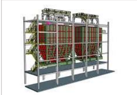
Ore Bins
Slurry Tanks / Conditioning Tanks
Can be reclaimed by front-end
loaders or bucket-wheel
reclaimers
Stockpiles
• Used as intermediate between
crushing and grinding
circuits
• They allow the steady discharge of
ore w/o
segregation or choking
• Sloping-bottom bins for
easily
oxidized ore
Ore Bins
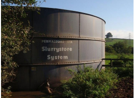
• For storing suspensions of fine
solids with provisions for
agitation
for suspension of solids or
prerequisite chemical reactions
Slurry Tanks/Conditioning Tanks
ORE FEEDING
Desired for delivery of uniform stream of ore
• Unnecessary for cases when succeeding operations have
same
rates of flow
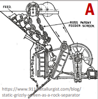
• Used for smooth control of bin discharge
• Consist of curtain of heavy loops of chain which when moves,
the ore begins to
slide
A. Chain Feeders
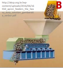
• Essentially a conveyor with abrasion-resistant steel pans attached
in series
• Most widely used feeder for coarse materials
B. Apron Feeders
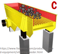
• Remove fines from coarse
particles before crushing
•
“Scalping” the ore to prevent
consolidation of fines
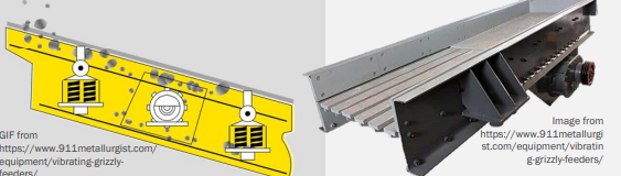
C. Vibrating Grizzlies
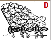
• Long elliptical bars in alternate
vertical and horizontal
positions
all rotating in one direction
• Rocking action
sifts the ore; the
fines fall through to a conveyor,
the
coarsest tumbles across to
crushe
D. Elliptical Bar Feeder
Hand Sorting
used when in abundance of cheap manual labor, or additional equipment installation is not economically justified
Magnetic Separators
situated above conveyors to pick up large pieces of tramp iron and steel; used w/ metal detectors
Vibrating Scalping Screens
removal of wood from pulp (wood causes choking)
Washing
▪ removal of slimes (very fine particles)
• Uses high-pressure
water jets over vibrating screens
Measures of Efficiency
DEGREE OF LIBERATION
MESH-OF-GRIND
PARTICLE SIZE ANALYSIS
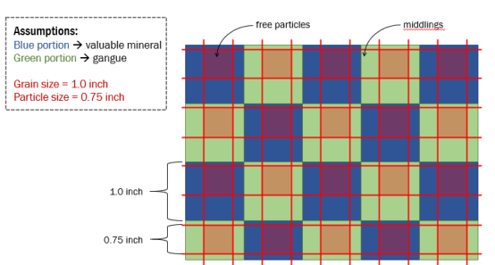
DEGREE OF LIBERATION
The percentage of a mineral or phase occurring as free particles in relation to the total of the minerals in the ore
MESH-OF-GRIND
The size up to which the ore is ground to ensure
sufficient
liberation of wanted mineral
• Normally taken as
80% passing product
• Balance between liberation and economics
(longer grinding duration =
higher costs)
PARTICLE SIZE ANALYSIS
Control of quality of grinding
• Measure of degree of
liberation
• Determining the optimum feed size
•
Establishing the grinding limit to reduce losses